JavaFX MeshViewの扱いかた
MeshViewはJavaFXの3次元モデルを表示するためのオブジェクトです。
たくさんの3角形を定義してテクスチャを貼りつけ、様々な形状を表示させることができます。
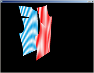
Meshの定義手順
MeshViewを定義する前に、まずTriangleMeshを作ります。メッシュには3つのデータを入れます。
3角形を構成する3次元点(points)、貼りつける画像を切り取るための2次元点(TexCoords)、三角形を構成する点(Faces)
pointsの設定
pointsは、floatの配列とし、各点のx,y,z値を順に入れます。下のような4点を格納する場合、
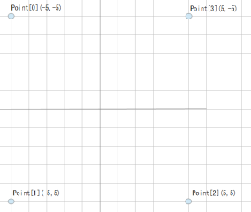
double x = 5.;
double y = 5.;
double z = 0.;
Point3D[] point = new Point3D[4];
point[0] =new Point3D( -x , -y , z );
point[1] =new Point3D( -x , y , z );
point[2] =new Point3D( x , y , z );
point[3] =new Point3D( x , -y , z );
下のように格納します。
float[] points = new float[ point.length*3 ];
int i=0;
for(int ii=0;ii<point.length;ii++){
points[i] = (float)point[ii].getX();i++;
points[i] = (float)point[ii].getY();i++;
points[i] = (float)point[ii].getZ();i++;
}
TexCoordsの設定
TexCoordsもfloatの配列ですが、2次元の点、x,yの値を順に入れてゆきます。
pointsの点と同じ数だけの点を定義するので、配列の長さは2/3になります。
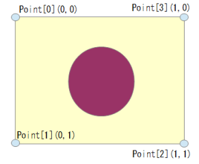
座標の値は、上のように貼りつける画像の左上を0,0、右下を1,1とします。0~1の範囲を外れると、画像をタイル状に並べて延長した画像がはめ込まれます。
pointsのx,y座標を取り出して、最大座標を1、最小を0となるように調整して定義すると、下記のようになります。
float[] texCoords = new float[ point.length*2 ];
i=0;
for(int ii=0;ii<point.length;ii++){
texCoords[i] = (float)((point[ii].getX()+x)/x/2);i++;
texCoords[i] = (float)((point[ii].getY()+y)/y/2);i++;
}
Facesの設定
先に定義した2組の点を使って三角形を定義します。三角形は3つの点の配列番号を順に並べて定義します。
点の順番は、逆時計回りに並べると、向かっている側の面が表となります。
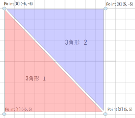
上のように3角形を2つ定義して、向かい側を表にする場合、{0,1,2, 2,3,0}とします。
また、テクスチャを貼る点の方も同時に設定します。Pointsの番号、TexCoordsの番号の順で交互に設定します。
points、TexCoordsの同じ配列番号を設定する場合は、{0,0,1,1,2,2, 2,2,3,3,0,0}
intの配列で、下記のように書きます。
int[] faces = {0,0,1,1,2,2,2,2,3,3,0,0};
TriangleMeshの定義
定義した3つをTriangleMeshに格納すれば2つの3角形で構成されるTriangleMeshを定義できます。
double x = 5.;
double y = 5.;
double z = 0.;
Point3D[] point = new Point3D[4];
point[0] =new Point3D( -x , -y , z );
point[1] =new Point3D( -x , y , z );
point[2] =new Point3D( x , y , z );
point[3] =new Point3D( x , -y , z );
float[] points = new float[ point.length*3 ];
int i=0;
for(int ii=0;ii<point.length;ii++){
points[i] = (float)point[ii].getX();i++;
points[i] = (float)point[ii].getY();i++;
points[i] = (float)point[ii].getZ();i++;
}
float[] texCoords = new float[ point.length*2 ];
i=0;
for(int ii=0;ii<point.length;ii++){
texCoords[i] = (float)((point[ii].getX()+x)/x/2);i++;
texCoords[i] = (float)((point[ii].getY()+y)/y/2);i++;
}
i=0;
int[] faces = {0,0,1,1,2,2,2,2,3,3,0,0};
TriangleMesh mesh = new TriangleMesh();
mesh.getPoints().addAll( points );
mesh.getTexCoords().addAll( texCoords );
mesh.getFaces().addAll( faces );
MeshViewの定義
定義したTriangleMeshをMeshViewに格納します。
画像を貼りつけなくても表示できますが、画像を貼りつける場合はPhongMaterialを作って追加します。
MeshView meshView = new MeshView();
meshView.setMesh( mesh );
meshView.setDrawMode( DrawMode.FILL );
PhongMaterial material = new PhongMaterial();
Image img = new Image("file:d:/work/java/maru.png");
material.setDiffuseMap( img );
meshView.setMaterial(material);
JavaFXMeshViewを表示するサンプルプログラム
作ったMeshViewを表示するプルグラムです。
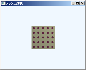
実行結果
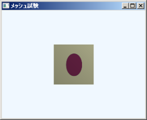
package tomojavalib.fx;
import javafx.application.Application;
import javafx.geometry.*;
import javafx.scene.*;
import javafx.scene.image.Image;
import javafx.scene.paint.Color;
import javafx.scene.paint.PhongMaterial;
import javafx.scene.shape.*;
import javafx.scene.transform.*;
import javafx.stage.Stage;
/**単純なJavaFX楽天 プログラム
*メッシュの作成
* */
public class App17 extends Application {
public static void main(String[] args) {
Application.launch(args);
}
@Override
public void start(Stage stage) throws Exception {
Scene scene = make3dScene();
stage.setScene(scene);
//タイトルの表示
stage.setTitle("メッシュ試験");
stage.show();
}
private Scene make3dScene(){
Group group = new Group();
//メッシュを置く
this.makeMesh( group );
//カメラを置く
PerspectiveCamera camera = new PerspectiveCamera( true );
//
カメラ
楽天 方向と位置
Translate cameratranslate = new Translate(0,0,-50);
//Rotate camerarotateX = new Rotate( 30 , new Point3D( 1 , 0 , 0 ) );
//Rotate camerarotateY = new Rotate( 30 , new Point3D( 0 , 1 , 0 ) );
//camera.getTransforms().add( camerarotateX );
//camera.getTransforms().add( camerarotateY );
camera.getTransforms().add( cameratranslate );
//視界の角度
camera.setFieldOfView( 30. );
group.getChildren().add( camera );
//点光源を置く
LightBase light = new PointLight();
light.setTranslateX( 30.0 );
light.setTranslateY( -30.0 );
light.setTranslateZ( -30.0 );
group.getChildren().add( light );
//Sceneの設定
Scene s3d = new Scene(group, 320, 240);
s3d.setFill(Color.ALICEBLUE);
s3d.setCamera( camera );
return s3d;
}
/**meshViewを作成してグループに追加する*/
private void makeMesh( Group group ){
double x = 5.;
double y = 5.;
double z = 0.;
Point3D[] point = new Point3D[4];
point[0] =new Point3D( -x , -y , z );
point[1] =new Point3D( -x , y , z );
point[2] =new Point3D( x , y , z );
point[3] =new Point3D( x , -y , z );
float[] points = new float[ point.length*3 ];
int i=0;
for(int ii=0;ii<point.length;ii++){
points[i] = (float)point[ii].getX();i++;
points[i] = (float)point[ii].getY();i++;
points[i] = (float)point[ii].getZ();i++;
}
float[] texCoords = new float[ point.length*2 ];
i=0;
for(int ii=0;ii<point.length;ii++){
texCoords[i] = (float)((point[ii].getX()+x)/x/2);i++;
texCoords[i] = (float)((point[ii].getY()+y)/y/2);i++;
}
//i=0;
int[] faces = {0,0,1,1,2,2,2,2,3,3,0,0};
TriangleMesh mesh = new TriangleMesh();
mesh.getPoints().addAll( points );
mesh.getTexCoords().addAll( texCoords );
mesh.getFaces().addAll( faces );
MeshView meshView = new MeshView();
meshView.setMesh( mesh );
meshView.setDrawMode( DrawMode.FILL );
PhongMaterial material = new PhongMaterial();
Image img = new Image("file:d:/work/java/maru2.png");
material.setDiffuseMap( img );
meshView.setMaterial(material);
group.getChildren().add( meshView );
return;
}
}
テクスチャーの歪み対策
貼りつける画像と作成するメッシュの形状が異なる場合、画像が歪んでしまいます。
下の例では、長方形の画像を正方形のメッシュに貼りつけたため、円が楕円になってしまいました。
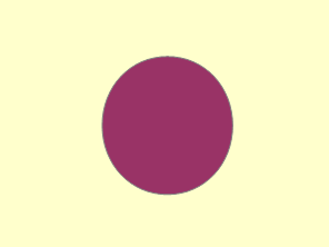

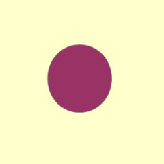
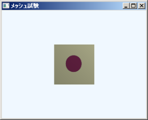
正方形の画像を正方形のMeshViewに貼りつければ歪むことはありません。
サンプルプログラムのようにMeshを平面で作る場合であれば、Meshのx,y座標を縮尺してTexCoordsの座標とし、正方形の画像をあてはめれば、歪みを無くすことができます。
繰り返し形状
TexCoordsの座標が0~1の範囲になければ、画像をタイル状に並べた表示となるので、市松模様や水玉模様など、同じ形が並ぶテクスチャーを作る場合、1つの模様の画像を用意するだけで済みます。
変更前
texCoords[i] = (float)((point[ii].getX()+x)/x/2.);i++;
texCoords[i] = (float)((point[ii].getY()+y)/y/2.);i++;
変更後
texCoords[i] = (float)((point[ii].getX()+x)/2.);i++;
texCoords[i] = (float)((point[ii].getY()+y)/2.);i++;
実行結果
変更前

変更後
最終更新日: 2017-03-08 08:10:57